Minnetronix Medical’s Nick Smith was featured recently in Medical Design & Outsourcing magazine for his article on design for manufacturing (DFM) strategies for alignment and testing in optical systems.
Smith, a principal opto-mechanical engineer at Minnetronix Medical, touched on how to make design-for-manufacturing (DFM) decisions specifically for optical-based medical device systems, which are fraught with tight tolerances and narrow performance windows.
Read the article at MD&O here, or the full article below:
It’s well understood that early design choices have a large impact on minimizing complexity, easing manufacturing, and reducing the cost of commercializing medical devices. Optimizing the onramp to production is key to derisking a device’s market introduction.
What often remains more nuanced, however, is how to make design-for-manufacturing (DFM) decisions specifically for optical-based medical device systems, which are fraught with tight tolerances and narrow performance windows.
In design reviews during the development of optical-based medical device systems, alignment and test plans should be presented which include details about in-process test fixtures and functional test pass/fail requirements. The goal of both alignment and optical testing is to ensure the manufactured devices meet the design modeled performance.
Custom alignment and test fixture development and implementation are often underestimated and delayed until the design is on the project’s critical path for the verification and validation (V&V) device build schedule. Best-practice development requires a multi-disciplinary team across commercialization stages to review and provide input to confirm the alignment and test plan is optimized for the manufacturing facility, labor skillset and time, intended volumes, and planned budget.
Optical system alignment
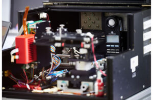
Optical subassembly illumination source alignment and power test fixture [Photo courtesy of Minnetronix Medical]One approach to system alignment is to incorporate several degrees of freedom (DOF) into the design that can be adjusted later. However, this can create a time-consuming, costly, and overly sensitive final device that requires intensive training for manufacturing. Robust devices with a high level of DFM alignment allow only the minimum DOF to meet performance goals.
Informed by the optical system nominal design and tolerance analysis, the optical and opto-mechanical teams should start with a block diagram to describe the minimal number of DOF required in the design, define the type of interfaces, and determine the proper range and resolution of the adjustments
The number of degrees of freedom can range from zero to many, including XYZ, rotation (θ), and tip/tilt. A system with zero DOFs is termed a “build-to-print” design, where the optical system tolerance analysis shows the stack up of the mechanical and optical component tolerances (without compensation DOFs) is sufficient for desired performance. This is typically the least expensive and simplest alignment method. When there are multiple DOFs for alignment, each DOF should be decoupled from the other so there are no compound alignments with multiple DOFs per adjustment. This approach reduces the need for intensive training and creates a systematic, efficient alignment process.
When incorporating off-the-shelf (OTS) components, they can be loosely controlled in a particular DOF that the tolerance analysis dictates is critical to performance. In this case, an alignment interface would be required (for example, a lens-focusing cell or an X/Y translation interface). Where there is a critical OTS interface that the design team does not control, an interface control document (ICD) is valuable to thoroughly describe the OTS part’s interface to the system.
Alignment interfaces and mechanisms vary and can have different implementations. Some mechanisms are built into the device permanently. Others are part of a fixture that is temporarily attached, such as a fine pitch screw for translation, gage block, or unique tool for accessibility. If temporary fixtures are used for alignment, the device-to-fixture interface design may add features to the final device design to better accommodate these alignment tools. Often these device-to-fixture interfaces include kinematic design features. Most interfaces also include a locking mechanism such as an UV cure adhesive or spring lock washer with a screw through an oversized hole. Locks can be permanent or reworkable.
Determining the proper range and resolution of the DOF is essential to incorporate into the design. This ensures the interfaces have enough designed-in travel in a particular direction and, when the user aligns the system, they can adequately find the best position with ease without relying on an individual’s “special touch” or taps with a wrench to finely knock the system into alignment. Developing unique tooling for alignment often alleviates this issue.
Optical testing

In-process optical performance manufacturing test fixture for endoscopes [Photo courtesy of Minnetronix Medical]Device-to-fixture interface design should also consider the planned optical testing equipment. Kinematic features, additional tapped holes, or locating diameters may need to be added to the device to control the interface used by the fixture during the in-process or final test.
Selecting the appropriate equipment for testing should also involve members from the optical, opto-mechanical, and manufacturing teams so the device build process is optimized. Some examples of equipment to consider are imaging targets, light sources, detectors, integrating spheres, controllers, and software tools to measure performance metrics.
Capitalizing, calibrating, and saving setup parameters on this equipment to create “golden fixtures” will prevent false pass/fails and future troubleshooting. Establishing objective pass/fail performance metrics allows the manufacturing team to have an efficient and clear process for creating high-quality devices at scale.
Here are some optical testing examples by metric and test fixture:
- Fiber coupling efficiency (optical power): Thermopile coupled to test fiber with real-time output
- Illumination spatial uniformity: Uniform Lambertian target at object, imaging system, and processing software
- Image focus: Resolution target at object with real-time MTF feedback
- Image distortion: Resolution target at object with processing software
- Color balance Standard color target with processing software
- Spectral characterization: Spectrophotometer
Avoiding commercialization setbacks

A multispectral imaging, illumination, and projection system with multiple degrees-of-freedom for enhanced visualization device[Photo courtesy of Minnetronix Medical]By following this approach to alignment and optical testing, commercialization plans can avoid major delays, expensive manufacturing costs, and redesign efforts. A phase-based approach to device development that includes a comprehensive optical team not only adds value but de-risks downstream commercial goals.
Early efforts by both design, development, and manufacturing teams, working together at the beginning stages of an optical device program, can address alignment and testing to ensure successful production, performance consistency, market launch, and scalability.

Nick Smith is a principal opto-mechanical engineer at Minnetronix Medical, a single-point provider for medical technology innovation that partners with medical device companies to accelerate breakthroughs in optical systems, fluid and gas management, RF energy, and stimulation and wearable devices. Smith is an optical products segment expert with more than a decade of experience in opto-mechanical system design and commercialization across broad applications in the medical device and capital equipment fields.
